GSoC, Symbolic planning techniques for recognizing objects domestic
#2
, Inverse Kinematics 15 Jun 2015What is inverse kinematics? : In this second post, although it may seem begin the house from the roof, let’s talk about how a robot moves its arms and hands in order to manipulate daily objects.
The ultimate goal of this work is make the robot to be able to recognize certain daily objects in a house (for example a mug), and to manipulate these objects with its effectors (hands). To do this, one of the things we need to implement is the inverse kinematics of the robot. Although this is the last step, we start by inverse kinematics to be easier and more intuitive than object recognition (besides that we have almost finalized the cinematic component in Robocomp).
###What does the inverse kinematics?
A recurring problem in robotics is to give to robots a certain autonomy in terms of movement. Focusing on a practical and realistic example, as is the trajectory of a robotic arm from an initial position to a target point, the question is how does the robot move its arm from the starting pose to the final pose? or what values take its engines arm to reach the final position? This is the typical problem of inverse kinematics, which is responsible for calculating the angular values of a kinematic chain composed engines (joints) of the arm to reach a target position.
But before we get down to work, we need to review a few concepts.
###Previous concepts
####kinematic chains
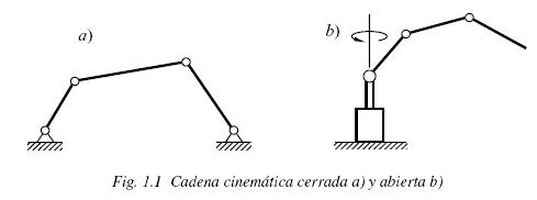
The first concept that we should be clear is the kinematic chain. The kinematic chain is a set of elements that produce motion, deforming the chain to adapt it to movement. Kinematic chains are composed of two elements:
joints: joints or motors that produce the movement. Each joint gives a degree of freedom.links: rigid segments that connect the joints together.
An example of kinematic chain in robotic is the arm of the robot, that is composed by all the motors that the robot has and the segments that connect this motors in order to create the arm form.
####Reference systems and Transformation coordinate.
One of the problems of robot manipulators is to know where their structural elements are arranged in the space in which they move. We therefore need a referral system that puts or position the elements of the robot in the workspace. So, a reference system is a set of agreements or conventions used by an observer to measure positions, rotations and other physical parameters of the system being studied. In our case, the arm of the robot is into the three-dimensional workspace (R³, with the axis X, Y and Z), where each components (for example, each joint) has one traslation (tx, ty, tz) and one rotation (rx, ry, rz). Therefore, the position of each component is given by a vector of six elements: P=[tx, ty, tz, rx, ry, rz] (the first three translational and three rotational recent). Normally, we represent the poses by homogeneous trasnformation matrices, which are of the form:
    | R  T |
P = | 0  1 |
where R is the rotation matrix and T the traslation coordenates.
One of the kinematic problems is that each motor (which can be moved and/or rotated with respect to the previous motor of the chain) has his own reference system, so if we want to calculate the position of a particular point or joint, we will have to make a number of changes (transformations) to move from one reference system to another. For example, if we have the newt arm:
X_1--------------X_2--------X_3-----O
       M_1>2          M_2>3    M_3>O
where X_n represents the position of the joints, - is the link that connects the joints, o is the end effector of the arm and M_n>m are the transformation matrices to change the reference system n to the system m, and we want to calculate the position of the end effector in the reference system of the joint X_1, we have to calculate this equation:
Po_inX_1 = M_2>1 * M_3>2 * M_o>3 * Po_inO.
###Problems to solve the inverse kinematics.
If the forward kinematics is responsible for calculating the position of the end effector in a kinematic chain, given some angular values for the joints, the inverse kinematics is just the opposite: it is responsible for calculating the angle values of the joints so the end effector reaches a position. This last problem is much more difficult to solve. So difficult that we are forced to use generic mathematical methods that try to approach an optimal solution iteratively within a reasonable time. We have opted for an iterative method known as the Levenberg-Marquardt or damped least squares algorithm. This method is used for solving nonlinear least squares problems where a solution to decrease an error function is sought.
###Inverse kinematics in Robocomp
As a result of the TFG, Inverse kinematics in Social Robots [1], since 2014 Robocomp has a component [2] that is responsible for calculating the inverse kinematics of the social robot Ursus [3], developed by Robolab. This component has undergone a big evolution, since it was created last year to now, and is more than likely to continue evolving to achieve inverse kinematics each finer and in less time.
Originally, this component receives three types of targets:
- POSE6D: It is the typical target with translations and rotations in the X, Y and Z axis. The end effector has to be positioned at coordinates (tx, ty, tz) of the target and align their rotation axes with the target, specified in (rx, ry, rz).
- ADVANCEAXIS: its goal is to move the end effector of the robot along a vector. This is useful for improving the outcome of the above problem, for example, imagine that the hand has been a bit away from a mug. With this feature we can calculate the error vector between the end effector and the mug, and move the effector along the space to place it in an optimal position, near the mug.
- ALIGNAXIS: Its goal is that the end effector is pointing to target without moving to it but rotated as the target. It may be useful in certain cases where we are more interested in oriented the end effector with the same rotation of the target.
To solve these various inverse kinematic problems, the component uses as main base the Levenberg-Marquardt algorithm proposed in the article SBA: A Software Package for Generic Sparse Bundle Adjustment by Lourakis and Argyros:
Input: A vector functon f: R^m → R^n with n≥m, a measurement vector x ∈ R^n and an initial parameters estimate p_0 ∈ R^m.
Output: A vector p+ ∈ R^m minimizing ||x-f(p)||^2.
Algorithm:
    k:=0;                 v:=2;                     p:=p0;
    A:=transposed(J)·J;   error:=x-f(p);            g:=transposed(J)·error;
    stop:=(||g||∞ ≤ ε1);  μ:=t*max_i=1,...,m (Aii)

    while(!stop) and (k<k_max)
         k:=k+1;
         repeat
               SOLVE (A+μ·I)·δ_p=g;
               if(||δ_p||≤ ε2·(||p||+ε2))
                    stop:=true;
               else
                    p_new:=p+δ_p
                    ρ:=(||error||^2-||x-f(p_new)||^2)/(transposed(δ_p)·(μ·δ_p+g));
                    if ρ>0
                        stop:=(||error||-||x-f(p_new)||<ε4·||error||);
                        p:=p_new;
                        A:=transposed(J)·J;    error:=x-f(p);    g:=transposed(J)·error;
                        stop:=(stop) or (||g||∞ ≤ ε1);
                        μ:=μ*max(1/3, 1-(2·ρ-1)^3);
                        v:=2;
                    else
                        μ:=μ*v;
                        v:=2*v;
                    endif
               endif
         until(ρ>0) or (stop)
         stop:=(||error||≤ ε3);
    endwhile
    p+:=p;
Where A is the hessian matrix, J is the jacobian matrix, g is the gradient descent, δ_p is the increments, ρ is the ratio of profit that tells us if we are approaching a minimum or not, μ is the damping factor, and t and ε1, ε2, ε3, ε4 are different thresholds. But the IK component of Robocomp adds several concepts to the original L-M algorithm, in order to complete the proper operation of the component:
- Weight matrix: that controls the relevance between the translations (in meters) and rotations (in radians) of the target. So, where
gwas calculated astransposed(J)·error, nowgistransposed(J)·(W·error) - Motors lock: when a motor reachs its minimun or maximun limit, we modified the jacobian matrix.
The new version of the inverse kinematics component simplifies the code of the old version and adds some more functionality:
- Executes more than once a target. The inverse kinematic result is not the same if the start point of the effector is the robot’s home or a point B near tho the goal point.
- Executes the traslations without the motors of the wrisht (only for Ursus). This makes possible to move the arm with stiff wrist, and then we can rotate easely the wrist when the end effectos is near the target.
Another improvement being studied is to include a small planner responsible for planning the trajectories of the robot arm, in order to facilitate the work of the IK component and reduce its execution time. However, one of the problems that the inverse kinematics can not solve by itself is the problem of gaps and imperfections of the robot. These gaps and inaccuracies make the robot move its arm toward the target position improperly, so that the robot “thinks” that the end effector has reached the target but in reality has fallen far short of the target pose.
In order to solve this last problem, we need visual feedback to correct the errors and mistakes introduced for the gaps and inaccuracies in the kinematic chain. The visualBIK component, developed during this project, is responsible for solve this visual feedback and correct the inverse kinematic, but we’ll talk about it in the next post.
Bye!
[1] Master Thesis, Universidad de Extremadura, Escuela Politécnica de Cáceres. Mercedes Paoletti Ávila. Cinemática Inversa en Robots Sociales. Directed by Pablo Bustos and Luis Vicente Calderita. July 2014. Download in https://robolab.unex.es/index.php?option=com_remository&Itemid=53&func=startdown&id=143
[2] inverse kinematics component repository: https://github.com/robocomp/robocomp-ursus/tree/master/components/inversekinematics
[3] C. Suárez Mejías, C. Echevarría, P. Núñez, L. Manso, P. Bustos, S. Leal and C. Parra. Ursus: A Robotic Assistant for Training of Patients with Motor Impairments. Book, Converging Clinical and Engineering Research on Neurorehabilitation, Springer series on BioSystems and BioRobotics, Editors, J.L Pons, D. Torricelli and Marta Pajaro. Springer, ISBN 978-3-642-34545-6, pages 249-254. January 2012. Download in https://robolab.unex.es/index.php?option=com_remository&Itemid=53&func=startdown&id=128
[4] Lourakis, M. I., Argyros, A. (2009). SBA: A Software Package for Generic Sparse Bundle Adjustment. Article of ACM Transactions on Mathematical Software, volume 36, issue 1, pages 1-30. Download in http://doi.acm.org/10.1145/1486527