GSoC, Symbolic planning techniques for recognizing objects domestic
#5
System Review 16 Aug 2015Full object manipulation system : In this post we will describe the full system developed for manipulating objects using a robotic arm. We start at the highest level, VisualIK (the correction system), and we will go down to the base of the system, the IK (which calculates the final angle of the joints of the robotic arm).

All the components that will be described below implement the InverseKinematics interface. This interface is defined by a series of data structures:
Pose6D: It represents a pose with three translations and three rotations [x, y, z, rx, ry, rz]WeightVector: It represents the weight vector of each element of Pose6D. This will help us later in the Levenberg-Marquardt algorithm.TargetState: It is the state when the targets reach the end of their execution by ik. It has some information like the elapsed time, the final error in translations and rotations and the values of each joint.Axis: This structure represents the Cartesian axes. It is necessary for certain special types of targets.Motor: This structure stores the name and the angular value of a motor of the kinematic chain.
Also, the interface defines a number of methods:
getTargetState: this method returns the state of one target, given the name of the robot part that executed the target and the numerical identifier of the target.getPartState: this method returns the state (if the part has pending targets or not) of one of the robot part (RIGHTARM, LEFTARM or HEAD).setTargetPose6D: This method is used to send targets to the ik. We need to indicate the part of the robot that will execute the target, the pose of the target and the weight vector of the pose. It returns the identifier of the target.setTargetAlignaxis: This method sends a special target for the IK. This target is achieved by aligning the end effector to the target axes. We must indicate the the part of the robot that will execute the target, the pose and the axes. It returns the identifier of the target.setTargetAdvanceAxis: This method sends another special target for the IK. The goal is that the end effector advance along a vector in the Cartesian system. We must indicate the part of the robot that will execute the target, the axes of the vector and the dist to advance. Like always, it return the identifier of the target.goHome: this method send a robot part to the idle position.stop: this method abort the execution of the targets of one of the robot part.setJoint: this method changes the angular value of one of the joint of the kinematic chain.setFingers: this method opens and closes the fingers of the end effector.
Now, we will describe the basic operation of our components.
###The visualIK component
The old VisualBIK component has been reorganized, resulting in the current visualik component. The basic principle of operation of the component remains, adding some improvements and changing its communication with the inversekinematics component, by the ikGraphGenerator component.
Its goal remains the same, correct errors produced by the inaccuracies of the joints in the IK. To this end, it bases its operation on a state machine:
IDLE: It is the resting state ofvisualik. The component is waiting to receive a target through one of the methods of its interface. When a target comes through the interface (stored in thecurrentTargetvariable), the state machine switches to INIT_BIK and prepares the global variables for the execution of correction.INIT_BIK: in this state, the visualik applies an initial correction to the target (Ec). This correction is based on experience in the correction of previous targets, so the first correction, having no previous experience, will be zero. Then, it sends the target to his proxy of kinematic, theikGraphGeneratorcomponent. Finally, the state of the machine is changed toWAIT_BIK.WAIT_BIK: in this state, thevisualikwaits the end of execution of the target by theikGraphGenerator. When theikGraphGeneratorfinishes executing the target, thevisualikchanges his state toCORRECT_ROTATION.CORRECT_ROTATION: It is the latest machine status. In this state is when thevisualikdoes all the calculations in order to correct the deviations and errors of the joints. The procedure is simple: a) by apriltags, thevisualikcalculates the visual pose of the end effector; b) then, it computes the error vector between the visual pose and the target pose (Ev); c) with this error vector Ev, thevisualikcorrects the target pose and sends the new position to theikGraphGeneratorcomponent; d) this process is repeated until the error achieved in translation and rotation is less than a predetermined threshold; e) finally thevisualikcalculates the error vector between the original target and the last corrected target (Ec), with this error the component realizes the first correction inINIT_BIK.
Here there is a scheme of the procedure performed by the visualik. It is very summarized to facilitate the understanding of the procedure by the reader:
1: procedure VISUAL CALIBRATION
2:    Xt = TargetArrives()
3:    Ct = Xt + Ec
4:    sendTargetToGIK(Ct)
5:    Xv = getAprilTagPose(robot)
6:    while (Ev = Xv- Xt) > threshold ^¬ timeOut() do
7:         Xi = getInternalPose(robot)
8:         Xc = Xi + Ev
9:         sendTargetToGIK(Xc)
10:        Xv = getAprilTagPose(robot)
11:   end while
12:   Ec = Xc - Xt
13: end procedure
Like all components developed by robocomp, the visualik needs a configuration file in which the components required (the ikGraphGenerator) and the components to subscribe (the apriltagsComp) and other configuration parameters are determined. In this case, a configuration file may have the following elements:
CommonBehavior.Endpoints=tcp -p 14537
# Endpoints for implemented interfaces:
InverseKinematics.Endpoints=tcp -p 10242

# Endpoints for interfaces to subscribe:
AprilTagsTopic.Endpoints=tcp -p 12938

# Proxies for required interfaces
InverseKinematicsProxy =inversekinematics:tcp -h localhost -p 10241 # `ikGraphGenerator`

InnerModel=/home/robocomp/robocomp/components/robocomp-ursus-rockin/etc/ficheros_Test_VisualBIK/ursus_bik.xml # the internal model of the robot environment

# This property is used by the clients to connect to IceStorm.
TopicManager.Proxy=IceStorm/TopicManager:default -p 9999
Ice.Warn.Connections=0
Ice.Trace.Network=0
Ice.Trace.Protocol=0
Ice.ACM.Client=10
Ice.ACM.Server=10
###The ikGraphGenerator component
As we explain in the previous post, the ikGraphGeneratorcomponent creates and stores a graph representing the work 3D space of the arm, where each node stores the euclidean space pose of the end effector and the configuration of the joints that compose the arm. So the ikGraphGenerator waits until the visualik send a target to him through the InverseKinematics interface. In this moment, the ikGraphGenerator performs four steps:
- the component searches the node A whose pose is closest to the initial end effector pose and moves the arm there.
- the component finds in the graph the node B whose pose is closest to the target position, disabling those nodes which would make the robot’s arm collide with external objects.
- the component computes the shortest path between the node A and the node B and moves the end effector among the nodes to reach the node B.
- Finally, the component moves from the graph to the actual target sending the original target to the
inversekinematiccomponent and taking the final values of the joints.
The ikGraphGeneratorneeds a config file too:
CommonBehavior.Endpoints=tcp -p 14536
# Endpoints for implemented interfaces:
InverseKinematics.Endpoints=tcp -p 10241

InnerModel=/home/robocomp/robocomp/components/robocomp-ursus/etc/ursus.xml # the internal model of the robot environment

# Proxies for required interfaces
InverseKinematicsProxy = inversekinematics:tcp -h localhost -p 10240
JointMotorProxy = jointmotor:tcp -h localhost -p 20000

Ice.Warn.Connections=0
Ice.Trace.Network=0
Ice.Trace.Protocol=0
Ice.ACM.Client=10
Ice.ACM.Server=10
###The inversekinematic component
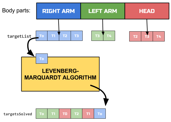
Finally, we will explain the basic component of the system, the inversekinematic component. As we said in the second post, this component receives three types of targets through the InverseKinematics interface:
POSE6D: the typical target with translations and rotations [tx, ty, tz, rx,ry, rz]. The end effector has to be positioned at coordinates (tx, ty, tz) of the target and align their rotation axes with the target, specified in (rx, ry, rz). This target arrives from the methodsetTargetPose6D.ADVANCEAXIS: its goal is to move the end effector of the robot along a vector. This target arrives from the methodsetTargetAdvanceAxis.ALIGNAXIS: Its goal is that the end effector has the axes aligned with the target. This target arrives from the methodsetTargetAlignaxis.
Targets received are stored into the queues of the corresponding robot part and they are executed by order of arrival. When the ik ends the execution of one target, it stores the target into the solved targets queue:
The config file of the inversekinematiccomponent is the next:
CommonBehavior.Endpoints=tcp -p 12207
# Endpoints for implemented interfaces:
InverseKinematics.Endpoints=tcp -p 10240

# Kinematic chain lists: they stores the joints names.
RIGHTARM=rightShoulder1;rightShoulder2;rightShoulder3;rightElbow;rightForeArm;rightWrist1;rightWrist2
RIGHTTIP=grabPositionHandR # end effector of the RIGHTARM

LEFTARM=leftShoulder1;leftShoulder2;leftShoulder3;leftElbow;leftForeArm;leftWrist1;leftWrist2
LEFTTIP=grabPositionHandL

HEAD=head_yaw_joint;head_pitch_joint
HEADTIP=rgbd_transform

InnerModel=/home/robocomp/robocomp/components/robocomp-ursus/etc/ursus.xml #Internal model of the robot environment

 # Proxies for required interfaces
JointMotorProxy = jointmotor:tcp -h localhost -p 20000

TopicManager.Proxy=IceStorm/TopicManager:default -p 9999
Ice.Warn.Connections=0
Ice.Trace.Network=0
Ice.Trace.Protocol=0
Ice.ACM.Client=10
Ice.ACM.Server=10
When visualik and ikGraphGenerator components submit their targets to the immediately below component, they store the identifier of the target and are waiting until the target be resolved, calling the method getTargetState. So, when the inversekinematic component ends one target execution, the ikGraphGenerator moves the arm with the values given by the inversekinematic component and then, the visualik continues with the corrections.
Having explained the handling system, the next post will explain the planning system developed by ROBOLAB to plan the robot’s actions.
Bye!