GSoC, Symbolic planning techniques for recognizing objects domestic
#6
grasping object
20 Aug 2015
Grasping object : This post will describe the planning system that implements Robocomp in order to provide to the robot a full functionality. In order for a robot be able to carry out a mission as “take the cup from the table and take it to the kitchen,” it needs something that in robotics calls planner. In this post we move away the issue of inverse kinematics and we dive into the field of artificial intelligence, making a slight revision of existing planners and delving into the planner using robocomp.
###Planning
As the name suggests, the planning is to generate plans. Plans to be executed by a robot in order to reach a goal. These objectives are often complex and require the execution of a series of steps that must be organized in the best possible manner to achieve the objective with an effort and within a reasonable time.
In order for a planner can build a series of plans, it needs an initial state of the world, a desired end state (or several) and a set of rules. For example, take the objective of frying an egg. We start with an initial world consisting of a kitchen with the necessary elements: an egg with a dozen eggs, a can of oil, a frying pan, a slotted spoon, a plate and a stove. And we have a set of rules, like to pour oil, to water plants, to crack egg, to stir, to serve, to light fire and to put the fire out. The duty of the planner is to select and order those rules that allow us to go from the initial state of the world (with raw eggs) to the final state in which a fried egg is served on a plate. Thus, the planner would eliminate the rule of “to water plants”, and would order the rest of rules as follows:
to light fire: in order to light the stove.to pour oil: to pour oil into the panto crack egg: to crack the egg and throw it into the panto stir: to catch the slotted spoon and to go stirring the oil for frying the egg well.to put the fire out: when the egg is fried the stove is turned off.to serve: to serve the fried egg on the plate
With these steps (very simplified) we get that our robot prepares us a fried egg… Although the example is miserable, we can see that any action we do and that we find it easy to execute, for a robot is quite complicated. That is why planning is a very complex field of artificial intelligence.
###Planning Domain Definition Language (PDDL)
This section will introduce the reader slightly in the planning language more used in artificial intelligence: PDDL. It was created in 1998 by Drew McDermott and his team for use in that year’s edition of International Planning Competition. The aim of PDDL is to standardize the planning languages for greater reuse of planning domains. Its operation is relatively simple:
Take for example, the following domain to create geometric shapes: We presume that in our initial world there is always a vertex node. The rules increase the number of vertices nodes to create geometric identities. For example, the segment rule creates from the initial node a line segment, the rule triangle creates from the line segment an equilateral triangle, the rule “square” creates from the equilateral triangle a square… and so on until an octagon. In the PDDL file, the rules would be:
(define (domain AGGL)
(:predicates
            (firstunknown ?u)
            (unknownorder ?ua ?ub)

            (isA ?n) # IS A NODE?
            (isB ?n)
            (isC ?n)
            (isD ?n)

            (union ?u ?v) # TWO NODES ?u AND ?v are united?
    )

    (:functions
            (total-cost)
    )

    (:action segment
            :parameters ( ?va ?vListAGMInternal ?vlist0 )
            :precondition (and (isA ?va) (firstunknown ?vlist0) (unknownorder ?vlist0 ?vListAGMInternal) (not(= ?vListAGMInternal ?vlist0)) )
            :effect (and (not (firstunknown ?vlist0)) (not (unknownorder ?vlist0 ?vListAGMInternal)) (firstunknown ?vListAGMInternal) (isB ?vlist0) (union ?va ?vlist0) (increase (total-cost) 1)
            )
    )

    (:action triangle
            :parameters ( ?va ?vb ?vListAGMInternal ?vlist0 )
            :precondition (and (isA ?va) (isB ?vb) (firstunknown ?vlist0) (unknownorder ?vlist0 ?vListAGMInternal) (not(= ?vListAGMInternal ?vlist0)) (union ?va ?vb) )
            :effect (and (not (firstunknown ?vlist0)) (not (unknownorder ?vlist0 ?vListAGMInternal)) (firstunknown ?vListAGMInternal) (isC ?vlist0) (union ?vb ?vlist0) (union ?vlist0 ?va) (increase (total-cost) 1)
            )
    )

    (:action square
            :parameters ( ?va ?vc ?vb ?vListAGMInternal ?vlist0 )
            :precondition (and (isA ?va) (isC ?vc) (isB ?vb) (firstunknown ?vlist0) (unknownorder ?vlist0 ?vListAGMInternal) (not(= ?vListAGMInternal ?vlist0)) (union ?va ?vb) (union ?vb ?vc) (union ?vc ?va) )
            :effect (and (not (firstunknown ?vlist0)) (not (unknownorder ?vlist0 ?vListAGMInternal)) (firstunknown ?vListAGMInternal) (isD ?vlist0) (union ?vc ?vlist0) (union ?vlist0 ?va) (not (union ?vc ?va)) (increase (total-cost) 1)
            )
    )
  )
To represent the initial world from which we start and the final world that we want to go, we should implement a file like this:
(define (problem myProblemPDDL)

    (:domain AGGL ) # planning domain ---> set of rules
    (:objects
            A_1
            unknown_0
            unknown_1
            unknown_2
            unknown_3
    )

    (:init
            (= (total-cost) 0)
            (firstunknown unknown_0)
            (unknownorder unknown_0 unknown_1)
            (unknownorder unknown_1 unknown_2)
            (unknownorder unknown_2 unknown_3)
            (isA A_1) # ---->  there is a initial vertex node
    )

    (:goal
            (exists ( ?A_1001 ?B_1002 ?C_1003 ?D_1004 ) # -----> we want a final world with a square
                    (and
                            (isA ?A_1001)
                            (isB ?B_1002)
                            (isC ?C_1003)
                            (isD ?D_1004)
                            (unido ?A_1001 ?B_1002)
                            (unido ?B_1002 ?C_1003)
                            (unido ?C_1003 ?D_1004)
                            (unido ?D_1004 ?A_1001)
                    )
            )
    )
    (:metric minimize (total-cost))
  )
This language proves to be relatively intuitive, easy to develop and test. However, in Robocomp we opted to do our own planning language: AGM.
###Active Grammar-based Modeling
AGM is the result of Luis Manso’s PhD thesis that “dealt with making software systems for robots more scalable, flexible and easier to develop using software engineering for robotics […] and enhancing active perception in robots using a grammar-based technique named active grammar-based modeling and a specially tailored novelty-detection algorithm named cognitive subtraction”1. To not extend much this post, you can check the working of the AGM on its official website. We will target only that AGM proves to be a useful graphical tool to program rules and to test domains and problems, and its grammar has a reminiscent of the PDDL language (has a AGM to PDDL converter). Let’s look at the same example as before but now in AGM:
This would be the set of rules in a .aggl file:
// START OF THE FILE:
segment : active(1)
{
    {
            a:A(-175,-15)
    }
    =>
    {
            a:A(-415,-5)
            b:B(-150,-5)
            a->b(union)
    }
}

triangle : active(1)
{
    {
            a:A(-330,-10)
            b:B(-70,-15)
            a->b(union)
    }
    =>
    {
            a:A(-440,170)
            c:C(-270,10)
            b:B(-70,170)
            a->b(union)
            b->c(union)
            c->a(union)
    }
}

square : active(1)
{
    {
            a:A(-385,80)
            c:C(-245,-125)
            b:B(-105,80)
            a->b(union)
            b->c(union)
            c->a(union)
    }
    =>
    {
            a:A(-460,125)
            c:C(-155,-45)
            b:B(-150,125)
            d:D(-460,-40)
            a->b(union)
            b->c(union)
            c->d(union)
            d->a(union)
    }
}
The initial world model is stored in a xml file:
<AGMModel>
    <symbol id="1" type="A" />  #There is only a vertex node (symbol) with the identifier "1" and te type "A"
</AGMModel>
The goal or target world is stored in another xml file:
<AGMModel>
    # NODES:
    <symbol id="a" type="A" />
    <symbol id="b" type="B" />
    <symbol id="c" type="C" />
    <symbol id="d" type="D" />
    # LINKS BETWEEN NODES (RELATIONSHIPS)
    <link src="a" dst="b" label="union" />
    <link src="b" dst="c" label="union" />
    <link src="c" dst="d" label="union" />
    <link src="d" dst="a" label="union" />
</AGMModel>
###Component architecture
Explained more or less the planners, we will explain the architecture of components developed by robocomp for the robot to be able to carry out actions. Oversimplifying the question in order to that the reader make a clear idea of how the architecture works, we can say that this architecture is divided into three levels:
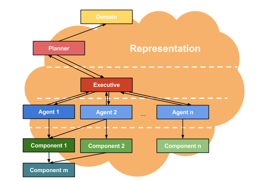
- First we need a problem domain (a set of rules), like problems in a home environment and a representation of the environment (a model of the robot and its environment).
- In the top we have the AGM planner. Given an initial world and an objective world, it is in charge of generating a plan to reach the goal with the domain defined.
- In the second label, we have a special component, the
executive. Basically he is responsible for transmitting the plan generated by the planner to the lower components. These components perform their actions and alter the representation of the environment. so the executive will have to call the scheduler to verify that these changes on the environment are correct and possible. If the changes are verified, the executive will update the representation. - In the third label we have the agent components. These are the components that receive the orders of the executive. They uses the operations of the lower component to change the representation. When they finish their execution, they publish the changes in order to be analyzed by the executive.
- In the botton we have the basic components. They are those who perform basic calculations. For example, our
inversekinematiccomponent, ourvisualikcomponent and ourikGraphGeneratorcomponent are in this level.
So the challenge that we have to complete is to create an agent that uses our three inverse kinematics components in order to reach a goal: that the robot take a cup. This component is called graspingAgent and is currently being developed by the laboratory. I would like to delve into its operation, but we still needs to implement many things and GSoC is coming to an end :(
It’s a shame to have to say goodbye with the work so close to being finished. But it doesn’t matters, the next year the robot will be serving coffee to Robolab guys XD.
Bye!
